Understanding DTE & DCE: SystemVerilog's Perspective
Intro#
RS-232 is a common electrical interface standard for communications, often physically presented as a DE-9 connector, and people today consistently run UART over it. But with a closer look at the standard TIA/EIA-232-F, readers will find some weird concepts like DTE and DCE. They often appear in many specifications published by TIA.
Searching DTE & DCE on the internet, people tend to present PCs and MODEMs connected to PSTN and assert that
Computers are DTE while MODEMs are DCE.

Dial-up Internet Access
This seems a bit far from the era, so are they abandoned? Not really.
Even if modern embedded software developers only encounter software problems about UART in TTL voltage levels, where there are few pins with no RS-232 voltage levels at all, they will still be exposed to these traditional terms unexpectedly in online documentation.
In this post, I will discuss the motivation of differentiating DTE & DCE and how people today weaken them, then manifest the potential benefits of applying them in digital design, using SystemVerilog.
Motivation#
The motivation behind DTE & DCE is simply that we are defining an interface between two devices. That’s it!
Interface is Bundled Wires with Directions#
This is not generally true. For example, I2C features a bidirectional bus. But for any given instant, the direction should be definitive since signal timing is well defined in the specification.
Let’s have a look at the common SPI interface definition.
| SPI Interface Name | Meaning | Direction |
|---|---|---|
CS | Chip Select | Main → Sub |
SCLK | Serial Clock | Main → Sub |
MOSI | Main Out, Sub In | Main → Sub |
MISO | Main In, Sub Out | Sub → Main |
That is the key point here. To clarify the signal direction, the standard has to classify devices and define the flow between them.
The same applies to RS-232. Here is a common definition for DTE and DCE.
DTEs produce data autonomously while DCEs only do data switching and signal conversion.
| RS-232 Interface Name (DE-9) | Meaning | Direction |
|---|---|---|
DCD | Data Carrier Detect | DCE → DTE |
RXD | Received Data | DCE → DTE |
TXD | Transmitted Data | DTE → DCE |
DTR | Data Terminal Ready | DTE → DCE |
GND | Ground | |
DSR | Data Set Ready | DCE → DTE |
RTS | Request To Send | DTE → DCE |
CTS | Clear To Send | DCE → DTE |
RI | Ring Indicator | DCE → DTE |
So it’s always expected to connect some DTE with another DCE together in RS-232, using a straight through cable.
Confusion and Weakening#
Here comes a dilemma, which makes the whole thing much confusing.
The most common use cases for RS-232 are peer-to-peer UART. For example, connecting a PC to an FPGA board with DE-9 connector makes a duplex channel between two devices. The FPGA board is collecting the sensor data and sending it through UART. The question is, which device is acting as a DCE?
In fact, they’re all DTE.
If you want to connect two DTEs together, you need a special crossover cable called null MODEM. This is not even a cable, it’s a fully qualified DCE.

Null MODEM
The differentiation between DTE & DCE claims that the TXD pin on a UART-capable device does not necessarily mean “transmitted data FROM this device”.
But connections between UART DTEs are dominant now, as a result, DTE & DCE are considered so old-school and confusing that modern equipments generally weaken them. So by the natural sense, a pin marked with TXD usually means “transmitted data FROM this device” today, since most of them are DTE in essence.
Ethernet (off-topic)#
Ethernet devices / ports are also classified into DTE & DCE, with straight through or crossover cables, but they are overwhelmingly weakened today in a different fashion.
Unlike RS-232 UART connections, you cannot claim which kind of device is the majority in Ethernet. To reduce the burden on terminal users of using correct cables, auto MDI-X is implemented to negotiate the link (especially for 10BASE-T / 100BASE-TX), no matter what kind of cables they’re using. Furthermore, PMA in 1000BASE-T natively defines that the cable pairs are bidirectional, and can identify many cases of polarity inversion.
For convenience, most Ethernet RJ-45 cables are straight through now, since the orders of cable pairs can be resolved and recognized by Ethernet transceivers. Thus there isn’t sensible distinction as per the connections between routers, switches, hubs and PCs. Same connections leads to same ports, same ports lead to no differences at all for end users.
Applications in Digital Design#
The concepts are not practical in real life because most of the devices are DTE now. But we can have internal DCEs when designing a complex logic on FPGA.
Here we demonstrate some examples in SystemVerilog.
Unified Interface#
This is a UART interface with standard MODEM signals.
| |
To make DTE and DCE come alive, we can use modport keyword to clarify the port direction for DTE and DCE variants.

Modports
| |
Null MODEM#
This is a construction of a null MODEM. The variant uart_io.dce is used because null MODEM itself is a DCE, and the other end of each port is some DTE.
| |
Furthermore we can even remove the variant for the port, the synthesizer will not work if there is a violation on signal directions. (e.g. connect a DTE and a DCE together using null MODEM)
| |
Mux#
Mux plays an important role in the next example. It allows the signal select_i to choose which device is connected to the main one. The sample code looks ugly because SystemVerilog does not natively support the interface mux, so developers should manually mux the wires.
| |
A (not quite) surprising result is that null MODEM can be redefined by a mux with static selection.
| |
Simple Mux-based Switch#
This is a simple mux-based switch. There is a PC and two extra DTEs (A, B) available. Now you can press the key to switch which DTE is connected to the PC.
I really love this example because it explains why the network nerds use “switch” as a term. This is a basic UART switch, with the same mechanisms behind L2 switch and L3 switch in complex computer networks.
| |
Complete Example#
Check alphabet.sv to see a complete example. The top module is shown as follows:
| |
Having 2 alphabet generators, one is uppercase while the other is lowercase, users can switch the generator after press the key. Remember to change the clock frequency based on your own boards.
| |
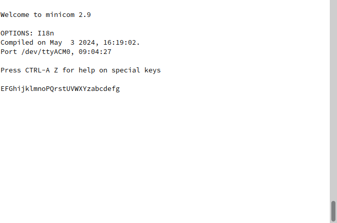
Result
Conclusion#
The concepts of DTE & DCE are invented to clarify the wires’ directions in communications interface.
But DTEs are dominant today and TXD RXD on DTEs convey a more natural meaning, so people care less about these concepts, and always use some kind of null MODEM.
Properly making use of these concepts in digital design makes unification possible and produces more elegant HDL code.